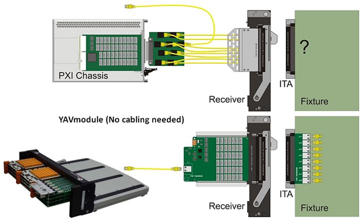
YAV90832 Multifunction board with 80 in/out
€919

YAV90832

Download the Catalogue.
Description
? 40 Input: 16 analog 10 Bit unipolar and three groups of 8 (24 in total) digital input with trigger level selectable.
? 32 Outputs (MOS) with an independent supply in groups of 8 protected and monitored.
? 4 analog output unipolar from 0?+15VDC
? 4 PWM output
? Powerful commands to read the values with triggered automatic filters
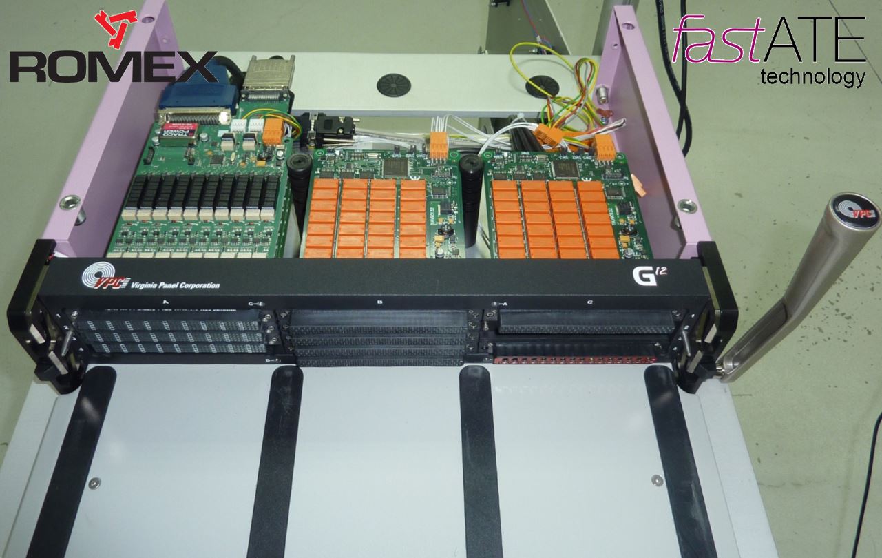
? VPC Tripaddle connector
? Can bus controlled, with address and speed selection
? Only 24Vdc power supply
? The module is automatically identified
? National Instruments LabView drivers
Applications
? Digital signals monitoring
? Analog Input and output
? 2 square pulses, shifted 90�, encoder emulator
? Fast counter from encoders with 1 or 2 square pulses, shifted 90�
? Relay and/or load actuators
YAV90832 inputs and outputs are sharing the common of the 24Vdc power supply. This common must be connected to the DUTs common.
Analog inputs accept up to +30V voltages with an acquisition resolution of 10 bits +1. They are protected up to +50V.
Digital inputs are organized in groups of 8, conforming banks. The first bank has 16 inputs while a second one has 8 inputs. Each bank has a terminal to set the trigger level. The board has two reference outputs (+2,5V and +5V) to be used as trigger level, in a direct manner or through a voltage divider.
Digital Outputs are organized in groups of 8. Each group has an independent supply voltage pin. They can work from +11VDC to +45VDC, sourcing up to 600mA. Failure monitoring for each group is available.
6 outputs can be used either as powered digital outputs (from terminal 89 to terminal 96) or as modulated outputs: additional four analog ports (from 57 to 60) and four PWM ports (from 61 to 64) are available. When modulated outputs are being used (analog or PWM), the logical status of the digital outputs will be a squared wave which is ON time proportional to the value of that modulated output.
Digital inputs 21-23 and 22-24 can be set as incremental encoder inputs (two channel 90� quadrature, up to 1MHz)
Technical Data
| Parameter | Nhemonic | Conditions | Value | Units | ||
| M�n | Normal | M�x | ||||
| Analog input | ||||||
| Measurement voltage range | VAIN | 0 | 15 | VDC | ||
| Input impedance | RAIN | ? | 1.2 | ? | MOhms | |
| Resolution | MR | ? | 10 | ? | Bits | |
| Maximum uncertainty | �2 | Bit | ||||
| Digital PNP input | ||||||
| Input voltage | VDIN | 0 | 30 | VDC | ||
| Input impedance | RDIN | 100 | KOhms | |||
| Trigger level voltage for 1 logic (Selection Ref.) | VTRG | 2,5 | ? | 5 | VDC | |
| Encoder inputs | ||||||
| Trigger level voltage for 1 logic (Selection Ref.) | VDIN | 2,5 | ? | 5 | VDC | |
| Counting frequency (Port P3) (2 Encoders) | FMAX3 | >100.000 | Hz | |||
| Counting frequency (Port P5) (1 Encoder) | FMAX5 | >10.000 | Hz | |||
| Voltage references | ||||||
| Reference voltage 2V5 | VR2V5 | 2.475 | 2.500 | 2.525 | VDC | |
| Internal resistance | RR2V5 | 100 | ohms | |||
| Reference voltage 1V25 | VR10V | 1.237 | 1.250 | 1.2625 | VDC | |
| Internal resistance | RR10V | 100 | ohms | |||
| Digital PNP output | ||||||
| Current I | IOUT | Permanent | ? | 625 | ? | mA |
| Internal resistance | ROUT | ON mode | ? | 200 | ? | mOhms |
| Working voltage | VOUT | 11 | ? | 45 | VDC | |
| Working temperature | TWRK | 5 | ? | 65 | �C | |
| Analog output | ||||||
| Short-circuit current Source mode (V= 0V) | IOUTSource | Permanent | 16 | 16 | 16 | mA |
| Short-circuit current Sink mode (V= 0V) | IOUTSink | Permanent | 11 | 11 | 11 | mA |
| Internal resistance | ROUT | 100 | ohms | |||
| Output voltage | VOUT | 0 | ? | 10 | VDC | |
| PWM Output | ||||||
| Current | IOUT | Permanent | 625 | mA | ||
| Internal resistance | ROUT | 200 | mOhms | |||
| Working voltage | VOUT | 11 | 45 | VDC | ||
Ordering information
| Description | P/N |
| Multifunction board with 80 in/out YAV90832 | YAV90832 |
[youtube https://www.youtube.com/watch?v=YTRr1BOvVPg?rel=0]